


Introduction
A printed circuit board by itself does not do much.
It has copper traces, pads, vias, solder mask, and silkscreen. But until you place and solder the components onto it, it is still just a board. The moment resistors, capacitors, ICs, connectors, and other parts are mounted, it becomes a circuit card assembly, or CCA.
You may also see the term PCBA, which means printed circuit board assembly. In many practical contexts, CCA and PCBA describe the same idea: a completed electronic assembly built on top of a PCB.
This is the part that actually does the work.
A CCA can control a motor, process signals from a camera, manage power rails, connect sensors, run software, or move data between different parts of a system. You will find circuit card assemblies inside almost everything electronic: routers, industrial controllers, medical devices, automotive modules, robotics systems, power supplies, and single-board computers.
That last category matters a lot in embedded design. A rockchip single board computer, for example, is not just a processor on a board. It is a complete circuit card assembly with memory, power management, connectors, storage interfaces, high-speed routing, and many small components working together.
In this guide, we will break down what a circuit card assembly is, what components it includes, how it is manufactured, what types of CCAs exist, and what engineers need to watch for when designing or evaluating one.
Table of Contents
- What Is a Circuit Card Assembly?
- Essential Components of a Circuit Card Assembly
- How a Circuit Card Assembly Is Manufactured
- Types of Circuit Card Assemblies
- Advantages of Circuit Card Assemblies
- Where Circuit Card Assemblies Are Used
- Design Challenges and Reliability Considerations
- Troubleshooting Common Circuit Card Assembly Problems
- Conclusion
- Frequently Asked Questions
What Is a Circuit Card Assembly?
A circuit card assembly is a printed circuit board with electronic components mounted and soldered onto it.
The bare PCB provides the electrical structure. The components provide the function.
Think of the PCB as the road network. It defines where signals and power can travel. The components are the buildings, switches, sensors, processors, and power systems that make the board useful.
A finished CCA usually includes:
- a printed circuit board;
- passive components such as resistors and capacitors;
- active components such as ICs, diodes, and transistors;
- connectors;
- solder joints;
- mechanical supports or shielding when needed.
Once assembled, tested, and inspected, the CCA becomes a working electronic module.
That difference matters. A bare PCB is a manufactured substrate. A CCA is a functional electronic product or subassembly.
Essential Components of a Circuit Card Assembly
Most circuit card assemblies look different from each other, but they share the same basic building blocks.
A simple sensor board may only have a few passive components and a connector. A high-performance embedded board may include a processor, memory, PMICs, Ethernet PHYs, USB controllers, camera interfaces, and dozens of supporting components.
Either way, the core structure is the same.
Printed Circuit Board
The PCB is the foundation of the assembly.
It gives components a physical place to sit and provides the copper pathways that carry power and signals between them. Without the PCB, every connection would need to be wired manually, which would be slow, unreliable, and impossible to scale for modern electronics.
A PCB usually includes several layers:
- copper traces for routing signals and power;
- insulating substrate, often FR-4;
- solder mask to protect copper and prevent solder bridges;
- silkscreen markings for labels and component placement;
- vias that connect different copper layers.
Simple boards may have only one or two layers. More advanced CCAs often use four, six, eight, or more layers to support high-speed signals, controlled impedance, dense routing, and cleaner power distribution.
The PCB layout has a huge impact on the final assembly. Poor routing can create noise, voltage drops, EMI problems, thermal issues, or manufacturing defects. A good layout makes assembly easier and improves reliability.
Electronic Components
The components are where the circuit actually comes alive.
They can be tiny surface-mount parts, larger through-hole parts, fine-pitch ICs, or complex packages like BGAs. Each one performs a specific role in the circuit.
Common components include:
- resistors;
- capacitors;
- inductors;
- diodes;
- transistors;
- voltage regulators;
- microcontrollers;
- processors;
- memory chips;
- sensors;
- power management ICs.
Passive components such as resistors and capacitors may look simple, but they are everywhere on a CCA. They set voltage levels, filter noise, stabilize power rails, shape signals, and support IC operation.
Active components handle switching, amplification, logic, processing, sensing, or communication. These are the parts that usually define what the board actually does.
A modern embedded CCA may combine both worlds: hundreds of tiny passive parts around a few critical ICs. The larger chips attract the attention, but the small supporting components are often what make the system stable.
Connectors
Connectors are easy to overlook until they fail.
They let the circuit card assembly communicate with the outside world. That could mean power input, Ethernet, USB, HDMI, MIPI cameras, sensors, displays, antennas, fans, batteries, or another PCB inside the same product.
A connector has two jobs:
First, it must provide a reliable electrical connection.
Second, it must survive real-world use.
That second part is where many designs run into problems. A connector on a bench prototype may work perfectly. Put the same board inside a product with vibration, cable strain, repeated plugging, heat, dust, or moisture, and weak connector choices show up quickly.
Connector problems are also a common cause of field failures. A loose connector can interrupt power or data lines and create symptoms that look like software bugs, failed components, or a typical open circuit fault.
Good CCA design treats connectors as mechanical parts as much as electrical ones. Locking tabs, strain relief, board support, plating quality, and cable routing all matter.
Solder Joints
Solder joints are the small connections that hold the entire assembly together.
They provide both mechanical attachment and electrical conductivity between each component lead or pad and the PCB.
A good solder joint is easy to ignore. A bad one can ruin the whole board.
Common solder-related defects include:
- insufficient solder;
- solder bridges;
- cold solder joints;
- tombstoned components;
- cracked joints;
- voids under large pads or BGAs.
Some defects appear during manufacturing. Others develop after months or years of thermal cycling, vibration, or mechanical stress.
That is why inspection and testing matter so much in CCA production. The board may look complete, but a single poor solder joint can stop a signal, break a power rail, or cause an intermittent failure that is hard to reproduce.
Mechanical and Thermal Elements
Not every circuit card assembly is just electronics.
Many boards also include mechanical or thermal features, especially in industrial, automotive, computing, and power electronics applications.
These may include:
- heatsinks;
- thermal pads;
- metal shields;
- mounting holes;
- stiffeners;
- brackets;
- conformal coating;
- enclosure contacts;
- grounding clips.
High-power boards need to move heat away from regulators, processors, MOSFETs, and other hot components. RF and high-speed boards may need shielding. Industrial boards may need coatings to protect against humidity, dust, or corrosive environments.
A reliable CCA is not only an electrical design. It is also a mechanical and thermal design.
How a Circuit Card Assembly Is Manufactured
Designing a circuit card assembly is only half the job. The other half is building it consistently and reliably.
Modern electronics manufacturing is highly automated, but the process still requires careful planning and quality control. A small defect during assembly – such as poor solder paste coverage or a slightly misaligned component – can lead to failures that are difficult to diagnose later.
While production methods vary depending on the product, most CCAs follow the same basic workflow.
1. PCB Fabrication
Everything starts with the printed circuit board.
Before any components are installed, the PCB is manufactured with copper layers, vias, solder mask, silkscreen, and surface finishes such as HASL or ENIG. At this stage, it contains no electronic components – only the electrical pathways that will connect them later.
The quality of the PCB has a direct impact on the finished assembly. Poorly manufactured boards can introduce issues long before components are mounted.
2. Solder Paste Application
The next step is applying solder paste.
A stainless-steel stencil is placed over the PCB, and solder paste is spread across it. The paste passes through the stencil openings and lands only on the component pads.
Each deposit must be the correct size. Too little solder can create weak joints, while too much increases the risk of bridges forming between adjacent pads.
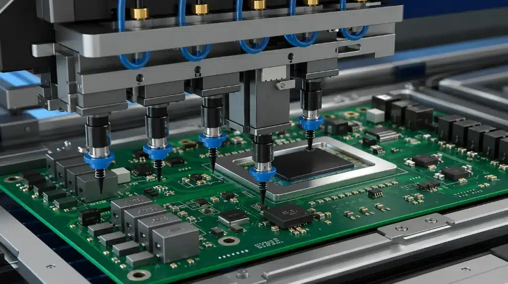
3. Component Placement
Once the solder paste is in place, automated pick-and-place machines begin populating the board.
Using high-speed vision systems, these machines pick components from reels or trays and position them with remarkable accuracy. Even complex boards with thousands of parts can be assembled in just a few minutes.
Placement accuracy becomes especially important for modern packages such as BGAs, QFNs, and fine-pitch processors, where even a slight offset may cause assembly defects.
4. Reflow Soldering
After placement, the board enters a reflow oven.
The temperature follows a carefully controlled profile that melts the solder paste without damaging components. As the solder cools, it forms permanent electrical and mechanical connections between the PCB and every surface-mount device.
Although the process looks simple, the temperature profile is critical. Heating too quickly or cooling too rapidly can affect solder quality and long-term reliability.
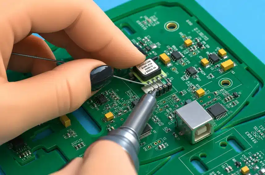
5. Through-Hole Assembly
Not every component is installed using surface-mount technology.
Larger connectors, transformers, relays, and other mechanically stressed components are often mounted using through-hole technology (THT). These parts are inserted into plated holes before being soldered manually or with automated wave-soldering equipment.
Many products combine SMT and THT on the same board to balance manufacturing efficiency with mechanical strength.
6. Inspection and Testing
Assembly doesn’t end when the solder cools.
Every production board should be inspected before moving to the next stage. Depending on the application, manufacturers may use:
- Automated Optical Inspection (AOI);
- X-ray inspection for hidden solder joints;
- In-Circuit Testing (ICT);
- functional testing;
- boundary scan testing.
Each method looks for different types of defects. AOI checks component placement and visible solder joints, while X-ray systems inspect packages such as BGAs where the connections cannot be seen from the outside.
Functional testing provides the final confirmation that the assembled board behaves as expected under real operating conditions.
Quality Matters at Every Step
Even highly automated production lines are only as good as the process behind them.
Successful CCA manufacturing depends on accurate PCB fabrication, consistent solder paste deposition, precise component placement, controlled soldering temperatures, and thorough inspection. Skipping quality checks at any stage increases the risk of defects reaching the final product.
For industries such as industrial automation, automotive electronics, medical equipment, and embedded computing, reliability isn’t optional – it’s built into the manufacturing process from the very beginning.
Types of Circuit Card Assemblies
Not every circuit card assembly is built the same way.
The right design depends on factors such as cost, component density, operating environment, manufacturing volume, and performance requirements. A simple sensor board has very different needs than an industrial controller or an edge AI computer.
Here are the most common types of CCAs.
Surface-Mount Assemblies
Surface-mount technology (SMT) is the standard for modern electronics.
Instead of inserting component leads through holes, SMT components are mounted directly onto the surface of the PCB. This allows manufacturers to place more components in less space while increasing production speed and reducing assembly costs.
Today, nearly every smartphone, laptop, networking device, and embedded computer relies primarily on SMT construction.
Through-Hole Assemblies
Through-hole technology predates SMT, but it still has an important role.
Components are inserted through drilled holes before being soldered to the opposite side of the board. The resulting mechanical connection is much stronger than a typical surface-mount joint.
For that reason, through-hole parts are commonly used for:
- power connectors;
- large capacitors;
- transformers;
- heavy switches;
- components exposed to mechanical stress.
Although THT requires more assembly time, it often delivers better durability in demanding environments.
Mixed-Technology Assemblies
Many products combine both approaches.
Processors, memory chips, and passive components are usually surface-mounted, while large connectors and power components remain through-hole.
This mixed approach gives designers the best of both worlds: compact layouts without sacrificing mechanical strength where it’s needed most.
Single-Sided and Double-Sided Assemblies
Some CCAs place components on only one side of the PCB. Others populate both sides to increase component density without increasing board size.
Double-sided assemblies are common in networking equipment, embedded computers, industrial controllers, and compact consumer electronics, where every square millimeter of PCB space matters.
High-Density Assemblies
As electronic devices become smaller and more powerful, component density continues to increase.
High-density circuit card assemblies often feature:
- fine-pitch IC packages;
- BGA processors;
- HDI PCBs;
- microvias;
- multiple copper layers;
- controlled impedance routing.
These designs demand tighter manufacturing tolerances and more advanced inspection techniques, but they make it possible to build compact systems with significantly greater computing power than previous generations.
Advantages of Circuit Card Assemblies
Circuit card assemblies have become the standard building block of modern electronics for one simple reason – they combine reliability, performance, and manufacturing efficiency.
Whether you’re designing a simple sensor board or a high-performance embedded computer, a well-designed CCA offers advantages that would be difficult to achieve with point-to-point wiring or older assembly methods.
Compact Design
One of the biggest advantages is component density.
Modern assembly techniques allow hundreds – or even thousands – of components to fit on a relatively small PCB. This makes it possible to build compact devices without sacrificing functionality.
As electronic products continue to shrink, efficient PCB layouts and dense circuit card assemblies have become essential.
Reliable Electrical Connections
A properly manufactured CCA provides stable electrical connections throughout the entire system.
Unlike hand-wired circuits, professionally assembled boards reduce the likelihood of loose wires, inconsistent connections, and assembly errors. Automated manufacturing also improves repeatability, ensuring every board performs the same way.
When combined with proper inspection and testing, a quality CCA can remain reliable for many years under normal operating conditions.
Faster Manufacturing
Automation has dramatically changed electronics production.
Modern pick-and-place equipment can position tens of thousands of components per hour with exceptional accuracy. Automated solder paste inspection, optical inspection, and functional testing further reduce manufacturing time while maintaining consistent quality.
For high-volume products, this translates into lower production costs and faster delivery.
Easier Maintenance and Replacement
Most electronic products are built from multiple assemblies rather than one large board.
If one module fails, technicians can often replace the entire circuit card assembly instead of repairing individual components. This approach simplifies maintenance and reduces equipment downtime, particularly in industrial and commercial systems.
Some failures still require board-level repair, but modular assemblies make servicing much more practical.
Better Performance
A well-designed PCB does more than hold components together.
Careful routing improves signal integrity, reduces electrical noise, minimizes voltage drops, and helps distribute power more efficiently. Thermal design also plays an important role by moving heat away from processors, power regulators, and other high-power components.
As clock speeds increase and interfaces become faster, PCB layout has become just as important as component selection.
Scalability
The same circuit card assembly can often serve as the foundation for multiple products.
Manufacturers frequently create several product variants using the same PCB while changing only memory size, connectors, firmware, or optional components. This reduces development costs and shortens time to market without requiring an entirely new hardware design.
Where Circuit Card Assemblies Are Used
It’s difficult to find modern electronics that don’t contain at least one circuit card assembly.
From small consumer devices to complex industrial equipment, CCAs provide the hardware platform that powers today’s electronic systems.
Consumer Electronics
Smartphones, laptops, tablets, routers, gaming consoles, televisions, and home appliances all rely on circuit card assemblies.
These products prioritize compact layouts, automated manufacturing, and high component density while keeping production costs under control.
Industrial Automation
Factories depend on reliable electronic hardware.
Programmable logic controllers (PLCs), motor drives, industrial gateways, machine vision systems, and robotic controllers all use CCAs designed to operate continuously in demanding environments.
Compared with consumer electronics, these assemblies often place greater emphasis on long-term reliability, thermal management, and resistance to vibration.
Automotive Electronics
Modern vehicles contain dozens of electronic control units.
Engine management, battery systems, infotainment, advanced driver assistance systems (ADAS), lighting, and climate control all depend on dedicated circuit card assemblies.
Automotive boards must withstand wide temperature ranges, constant vibration, and years of continuous operation.
Medical Equipment
Medical devices require an even higher level of reliability.
Patient monitors, imaging systems, infusion pumps, laboratory equipment, and portable diagnostic devices all rely on carefully manufactured CCAs that meet strict quality and regulatory requirements.
Every stage – from PCB fabrication to final testing -must be tightly controlled.
Aerospace and Defense
Aircraft, satellites, and military systems operate in environments where failure isn’t an option.
Circuit card assemblies used in these applications undergo extensive inspection, environmental testing, and qualification before entering service. Components are selected not only for performance but also for long-term reliability under extreme operating conditions.
Embedded Computing
Embedded systems have become one of the fastest-growing applications for circuit card assemblies.
Single-board computers (SBCs), industrial gateways, AI edge devices for real-time analytics, robotics platforms, and IoT controllers all integrate processors, memory, storage, networking, and power management onto a single assembly.
As these systems become more powerful, PCB design grows increasingly complex. High-speed interfaces, dense routing, multiple power domains, and thermal management all require careful engineering to ensure reliable operation.
Design Challenges and Reliability Considerations
Designing a circuit card assembly isn’t just about making the circuit work. It also needs to be manufacturable, reliable, and easy to test.
Many problems don’t appear until after production begins or products reach customers.
Some of the most common challenges include:
- maintaining signal integrity at high data rates;
- controlling electromagnetic interference (EMI);
- dissipating heat from high-power components;
- ensuring stable power distribution;
- selecting connectors that can withstand repeated use;
- preventing mechanical stress from damaging solder joints.
Designers also need to think about long-term reliability.
Temperature cycling, vibration, humidity, dust, and mechanical shock all affect electronic assemblies over time. Even small design decisions – such as connector placement or copper thickness – can influence how well a board performs after years of operation.
For that reason, successful CCA design combines electrical engineering, mechanical engineering, thermal analysis, and manufacturing expertise rather than focusing on any one discipline alone.
Troubleshooting Common Circuit Card Assembly Problems
Even a well-designed circuit card assembly can develop faults over time.
Some problems appear during manufacturing, while others show up only after months or years of operation. A systematic troubleshooting process helps narrow down the cause without replacing perfectly good components.
Start with a Visual Inspection
Many hardware issues can be identified before taking any measurements.
Look for obvious signs of damage, including:
- burnt components;
- cracked solder joints;
- damaged PCB traces;
- loose connectors;
- corrosion;
- missing or misaligned components.
A careful inspection often saves more time than immediately reaching for test equipment.
Verify Power First
If a board appears completely dead, always check the power rails before investigating individual components.
Confirm that the input voltage reaches the board and that voltage regulators are producing the expected outputs. Many failures that seem to involve processors or firmware are actually caused by missing or unstable power.
Test Signals Methodically
Once the power system has been verified, move on to the signal path.
Use a multimeter to check continuity where appropriate, and use an oscilloscope or logic analyzer when working with clocks, communication buses, or high-speed digital interfaces.
Rather than guessing where the problem is, follow the signal step by step until it disappears or behaves unexpectedly.
Don’t Ignore Mechanical Issues
Not every failure is electrical.
Connectors can loosen over time, vibration can crack solder joints, and repeated thermal expansion may eventually damage copper traces. These faults often appear intermittently, making them more difficult to reproduce than permanent failures.
If a board only fails after being moved, heated, or cooled, mechanical stress is often part of the problem.
Verify the Repair
Finding the fault isn’t the final step.
After replacing a component or repairing a connection, test the board under normal operating conditions. Verify that the original issue has been resolved and confirm that no new problems were introduced during the repair process.
A few additional minutes of testing can prevent another service call later.
Conclusion
Circuit card assemblies are the foundation of modern electronic hardware.
From consumer electronics and industrial automation to automotive systems and embedded computing, nearly every electronic device depends on one or more CCAs to provide processing, power distribution, communication, and control.
Although the technology behind today’s assemblies has become increasingly sophisticated, the basic idea hasn’t changed. A well-designed PCB, quality components, reliable solder joints, and careful manufacturing all work together to create hardware that performs consistently over years of operation.
Understanding how circuit card assemblies are designed, manufactured, and tested also makes troubleshooting much easier. Whether you’re evaluating a new product, developing embedded hardware, or diagnosing a failed board, knowing how a CCA is built helps you identify problems faster and make better engineering decisions.
Frequently Asked Questions
What is the difference between a PCB and a circuit card assembly?
A PCB is an empty printed circuit board that contains copper traces and mounting pads but no electronic components. A circuit card assembly is the finished board after components have been installed, soldered, inspected, and tested.
Is a circuit card assembly the same as a PCBA?
In most industries, yes.
The terms Circuit Card Assembly (CCA) and Printed Circuit Board Assembly (PCBA) are often used interchangeably. Both refer to a populated PCB that is ready to perform its intended function.
Why are solder joints so important?
Every electrical connection between a component and the PCB depends on a solder joint.
Poor solder quality can lead to intermittent failures, increased resistance, unreliable signals, or complete loss of functionality. That’s why modern production lines rely on automated inspection and functional testing to verify assembly quality.
Can a damaged circuit card assembly be repaired?
It depends on the type of failure.
Replacing connectors, passive components, or damaged ICs is often possible using the proper tools and techniques. However, severe PCB damage, multilayer trace failures, or extensive thermal damage may make replacement more practical than repair.
What causes most CCA failures?
Common causes include poor solder joints, damaged connectors, overheating, moisture, vibration, manufacturing defects, electrostatic discharge (ESD), and normal component aging.
Many of these issues can be minimized through good PCB design, proper manufacturing processes, and thorough testing before the product enters service.
