


Introduction
The Raspberry Pi Zero 2 W proves that a single-board computer doesn’t have to be large to be capable.
Despite measuring just 65 × 30 mm, it combines a quad-core 64-bit processor, wireless networking, and the same 40-pin GPIO header found on larger Raspberry Pi models. That makes it a popular choice for embedded systems, robotics, IoT devices, portable electronics, and custom hardware projects where space is limited.
The board may be small, but it offers impressive flexibility. Through its GPIO header, developers can connect displays, cameras, sensors, motors, communication modules, and countless other peripherals without requiring additional hardware.
As the single-board computer market continues to evolve- with newer platforms such as the Raspberry Pi 6 vs Rockchip generation pushing performance even further – the Raspberry Pi Zero 2 W remains one of the most affordable and widely supported options for compact embedded applications.
In this guide, we’ll explain the Raspberry Pi Zero 2 W pinout, break down the function of every major pin group, and show how the GPIO header is used in real-world engineering projects.
Table of Contents
- Raspberry Pi Zero 2 W Overview
- Understanding the 40-Pin GPIO Header
- Power Pins
- GPIO Pins
- GPIO Numbering
- I²C Interface
- SPI Interface
- UART
- PWM and PCM
- Choosing the Right Interface
- Practical GPIO Applications
- Best Practices for Using GPIO
- Common GPIO Mistakes
- Is the Raspberry Pi Zero 2 W Still Worth Buying?
- Conclusion
- Frequently Asked Questions
Raspberry Pi Zero 2 W Overview
Released as the successor to the original Raspberry Pi Zero series, the Zero 2 W delivers a significant performance boost while maintaining the same compact form factor.
At its core is the Broadcom BCM2710A1, a quad-core 64-bit Arm Cortex-A53 processor running at 1 GHz. Combined with 512 MB of LPDDR2 memory, it provides enough computing power for lightweight Linux applications, automation projects, media streaming, network appliances, and embedded control systems.
Key specifications include:
- Broadcom BCM2710A1 quad-core Cortex-A53 processor
- 512 MB LPDDR2 SDRAM
- 2.4 GHz 802.11 b/g/n Wi-Fi
- Bluetooth 4.2 with BLE
- Mini HDMI output
- Micro USB OTG port
- CSI camera connector
- MicroSD card slot
- 40-pin GPIO header
- HAT compatibility
Although its processing power is modest compared with today’s flagship SBCs, the Raspberry Pi Zero 2 W continues to strike an excellent balance between size, power consumption, and software support.
For many embedded applications, the GPIO header is far more important than raw CPU performance. It gives developers direct access to power rails, digital I/O, communication buses, and hardware peripherals, making the board suitable for everything from simple sensor interfaces to complete automation systems.
Like any modern circuit card assembly, the Raspberry Pi Zero 2 W integrates the processor, memory, power management circuitry, wireless module, connectors, and supporting components onto a compact multilayer PCB designed for reliable operation.
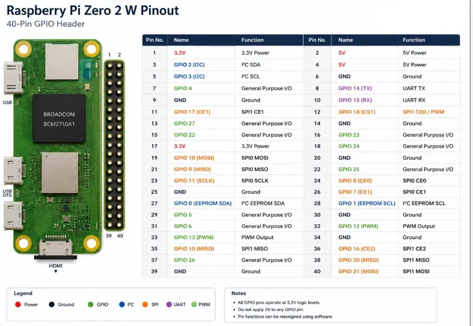
Understanding the 40-Pin GPIO Header
The 40-pin GPIO header is what makes the Raspberry Pi Zero 2 W much more than a tiny Linux computer.
While the processor runs applications and the operating system, the GPIO header allows the board to interact directly with external hardware. Through these pins, developers can read sensors, drive motors, communicate with displays, control LEDs, and interface with countless electronic devices.
One of the biggest advantages of the Raspberry Pi ecosystem is consistency. The Zero 2 W uses the same 40-pin header layout found on most full-size Raspberry Pi boards, allowing many HATs, expansion boards, and GPIO accessories to work without modification.
The header combines several different types of connections:
- power pins;
- ground (GND) pins;
- general-purpose input/output (GPIO) pins;
- I²C interfaces;
- SPI interfaces;
- UART communication;
- PWM outputs;
- PCM/I²S audio signals.
Although every pin has a physical location, many GPIO pins can perform more than one function. Depending on your software configuration, the same pin might act as a digital input, a serial communication line, or part of another hardware interface.
Understanding these alternate functions is essential when designing custom hardware or connecting multiple peripherals.
Power Pins
Several pins on the GPIO header provide power to external devices.
The Raspberry Pi Zero 2 W includes both 3.3 V and 5 V outputs, along with multiple ground connections distributed across the header.
These power pins make it easy to connect sensors, displays, small modules, and other low-power peripherals without requiring a separate power supply.
However, it’s important to understand their limitations.
The GPIO pins themselves operate at 3.3 V logic levels. Applying 5 V directly to a GPIO pin can permanently damage the processor. While the board exposes 5 V power pins, they should never be confused with the GPIO signal pins.
As a general rule:
- use 3.3 V for GPIO-compatible peripherals;
- use the 5 V pins only to power supported external devices;
- always connect a common ground between the Raspberry Pi and any external hardware.
Carefully checking the wiring before powering a circuit is one of the easiest ways to avoid damaging the board.
GPIO Pins
GPIO stands for General-Purpose Input/Output.
These programmable pins can be configured as either inputs or outputs, allowing the Raspberry Pi Zero 2 W to communicate directly with external electronics.
As outputs, GPIO pins can control LEDs, relays, transistors, buzzers, and other digital devices.
As inputs, they can read push buttons, limit switches, motion detectors, and digital sensors.
Most embedded projects rely on only a handful of GPIO pins, but having more available gives developers greater flexibility as projects grow in complexity.
Because the Raspberry Pi Zero 2 W shares its GPIO layout with larger Raspberry Pi models, code written for one board often works on another with little or no modification. This compatibility is one of the reasons the Raspberry Pi ecosystem has remained so popular among hobbyists, educators, and professional developers alike.
For projects that require additional interfaces, faster processors, PCIe connectivity, or AI acceleration, developers often move beyond the Zero series to larger boards such as the Rock Pi 5 development board. Even so, the GPIO concepts remain largely the same across most modern embedded platforms.
GPIO Numbering
One point that often confuses beginners is GPIO numbering.
Each pin on the header has both a physical pin number and a Broadcom (BCM) GPIO number.
For example:
Most modern Raspberry Pi software libraries use BCM numbering, while wiring diagrams often reference the physical pin locations.
Knowing which numbering scheme a project uses can save a great deal of troubleshooting time.
I²C Interface
I²C (Inter-Integrated Circuit) is one of the most commonly used communication interfaces on the Raspberry Pi Zero 2 W.
Instead of requiring a separate wire for every peripheral, I²C allows multiple devices to share the same two communication lines:
- SDA (Serial Data) for transferring data
- SCL (Serial Clock) for synchronization
This simple design makes I²C ideal for connecting several low-speed peripherals to a single board.
Common examples include:
- temperature and humidity sensors;
- OLED displays;
- real-time clock (RTC) modules;
- environmental sensors;
- GPIO expanders;
- EEPROM memory.
Each device has its own address, allowing several peripherals to communicate over the same bus without interfering with one another.
For many embedded projects, I²C offers the easiest way to add additional hardware while keeping wiring simple.
SPI Interface
When higher communication speeds are required, SPI is often the better choice.
Unlike I²C, SPI uses dedicated communication lines for data transmission and chip selection, allowing much faster data transfers with lower latency.
The Raspberry Pi Zero 2 W supports SPI through dedicated GPIO pins, making it suitable for devices such as:
- TFT and LCD displays;
- high-speed ADCs and DACs;
- flash memory;
- Ethernet controllers;
- radio modules;
- industrial communication peripherals.
The trade-off is that SPI requires more wiring than I²C, especially when multiple devices share the same bus.
For applications involving displays, data acquisition, or fast external peripherals, the additional complexity is usually worthwhile.
UART
UART (Universal Asynchronous Receiver-Transmitter) provides straightforward serial communication between the Raspberry Pi and other devices.
Unlike I²C or SPI, UART establishes a direct point-to-point connection using just two signal lines:
- TX (Transmit)
- RX (Receive)
UART is widely used for:
- debugging embedded systems;
- communicating with microcontrollers;
- configuring network equipment;
- GPS receivers;
- Bluetooth modules;
- industrial serial devices.
One of its biggest advantages is simplicity. Many engineers use UART as the first interface when bringing up a new embedded board because it provides immediate access to boot messages and diagnostic output.
PWM and PCM
Not every GPIO pin is limited to simple digital input and output.
Some pins can perform specialized functions, including Pulse Width Modulation (PWM) and PCM/I²S digital audio.
PWM
PWM allows the Raspberry Pi Zero 2 W to simulate analog output by rapidly switching a digital signal on and off.
Common applications include:
- LED brightness control;
- servo motors;
- DC motor speed control;
- cooling fans;
- audio generation.
By changing the duty cycle instead of the voltage itself, PWM provides precise control using standard digital pins.
PCM / I²S
PCM, also known as I²S, is designed for high-quality digital audio communication.
Instead of transmitting analog sound, it carries digital audio data between the Raspberry Pi and external audio hardware.
Typical devices include:
- DAC modules;
- audio codecs;
- digital microphones;
- amplifiers;
- external sound cards.
Although many hobby projects never use PCM, it becomes valuable when building media players, smart speakers, or custom audio equipment.
Choosing the Right Interface
Each communication interface serves a different purpose, and selecting the right one depends on the hardware you’re connecting.
There is no single “best” interface. The right choice depends on factors such as bandwidth, wiring complexity, latency, and the capabilities of the peripheral itself.
For many makers and engineers, the Raspberry Pi Zero 2 W offers an excellent balance between simplicity and flexibility. However, projects that require significantly more computing power, PCIe connectivity, multiple display outputs, or integrated AI acceleration may eventually outgrow compact SBCs. In those cases, choosing between a Raspberry Pi, a more powerful embedded board, or even a small desktop platform becomes an architectural decision rather than simply a hardware upgrade. A detailed Raspberry Pi vs Mini PC comparison can help determine which platform best matches your application’s performance and expansion requirements.
Practical GPIO Applications
The Raspberry Pi Zero 2 W is capable of far more than blinking an LED.
Its GPIO header makes it suitable for a wide range of embedded applications, from simple automation projects to complete control systems. Whether you’re building a prototype or deploying a finished product, the same GPIO pins can interface with hundreds of different peripherals.
Here are some of the most common use cases.
Sensor Integration
One of the first applications for the GPIO header is connecting sensors.
Environmental sensors, motion detectors, proximity sensors, light sensors, and pressure sensors can all be connected using GPIO, I²C, or SPI.
This makes the Raspberry Pi Zero 2 W a popular choice for:
- weather stations;
- smart home devices;
- greenhouse monitoring;
- environmental data logging;
- industrial sensing.
Because Linux provides mature driver support for many popular sensors, developers can often begin collecting data within minutes.
Robotics and Motor Control
GPIO pins are frequently used to control external hardware.
Although the GPIO pins themselves cannot drive motors directly, they can control motor drivers, H-bridge modules, relays, and servo controllers.
Typical robotics projects include:
- mobile robots;
- robotic arms;
- conveyor systems;
- automated feeders;
- pan-and-tilt camera platforms.
PWM outputs also allow smooth speed control for compatible motor drivers and servo systems.
Home Automation
Compact size and built-in wireless connectivity make the Raspberry Pi Zero 2 W well suited for home automation.
Many developers use it to control:
- lighting systems;
- smart switches;
- security sensors;
- irrigation controllers;
- garage doors;
- HVAC equipment.
Instead of acting as a standalone controller, the board often communicates with larger automation platforms using Wi-Fi while interacting with local hardware through its GPIO header.
Industrial Prototyping
Although industrial deployments often use dedicated embedded controllers, the Raspberry Pi Zero 2 W remains an excellent prototyping platform.
Engineers frequently use it to validate hardware designs, test communication protocols, or develop proof-of-concept systems before moving to production hardware.
The extensive software ecosystem, large developer community, and broad peripheral support allow new ideas to be tested quickly with minimal hardware development.
Best Practices for Using GPIO
Working with GPIO is straightforward, but a few simple habits can prevent many common hardware problems.
Never Apply 5 V to GPIO Pins
The GPIO pins use 3.3 V logic.
Applying 5 V directly to a GPIO signal pin can permanently damage the processor. If you’re connecting external hardware that operates at 5 V, use a proper level shifter or interface circuit whenever necessary.
Double-Check Pin Numbers
Confusing physical pin numbers with BCM GPIO numbers is one of the most common mistakes made by beginners.
Before connecting hardware, verify both the wiring diagram and the software configuration to ensure they reference the same numbering scheme.
Power External Devices Properly
The GPIO header can power small peripherals, but it is not designed to supply large amounts of current.
Motors, LED strips, pumps, and other high-power devices should always use an external power supply rather than drawing power directly from the Raspberry Pi.
Keep Wiring Organized
Neat wiring isn’t just about appearance.
Shorter wires reduce electrical noise, organized cables simplify troubleshooting, and secure connections help prevent accidental disconnections during testing.
As projects become more complex, proper cable management becomes increasingly important.
Common GPIO Mistakes
Even experienced developers occasionally make wiring mistakes.
Fortunately, most can be avoided with careful planning.
Some of the most common issues include:
- connecting peripherals to the wrong GPIO pin;
- reversing power and ground connections;
- mixing BCM and physical pin numbering;
- exceeding current limits;
- forgetting pull-up or pull-down resistors;
- accidentally creating short circuits while wiring.
Another frequent mistake is assuming every Raspberry Pi accessory is compatible with every project. While the GPIO header remains largely consistent across Raspberry Pi boards, power requirements, available interfaces, and processing capabilities vary significantly between models.
Before starting a new design, it’s worth considering whether the Zero 2 W provides enough computing power for future expansion. Applications involving machine vision, multiple cameras, edge AI, or high-speed networking may benefit from newer embedded platforms, including upcoming RK3688 SBC platforms expected to offer substantially higher performance than today’s entry-level SBCs.
Is the Raspberry Pi Zero 2 W Still Worth Buying?
The Raspberry Pi Zero 2 W was never designed to compete with high-performance single-board computers.
Its strength lies elsewhere.
The board offers an excellent balance of size, power consumption, affordability, and software support. For applications such as IoT devices, simple automation systems, portable electronics, and embedded controllers, it remains one of the best options available.
Its biggest advantage is the Raspberry Pi ecosystem itself. Years of community support mean that tutorials, software libraries, accessories, and HATs are readily available, making development faster and easier.
That said, hardware requirements continue to evolve.
Modern embedded applications increasingly rely on AI inference, high-resolution cameras, multiple displays, faster networking, and PCIe expansion. These workloads often exceed what a compact board like the Zero 2 W was designed to handle.
As a result, many developers now choose more powerful SBCs for demanding applications while continuing to use the Zero 2 W for lightweight embedded projects where its compact size and low power consumption remain significant advantages.
Conclusion
The Raspberry Pi Zero 2 W demonstrates that a compact board can still be remarkably capable.
Its familiar 40-pin GPIO header, broad software compatibility, built-in wireless connectivity, and efficient quad-core processor make it an excellent platform for learning embedded development as well as building real-world hardware projects.
Understanding the GPIO header is about more than memorizing pin numbers. Once you know how the different interfaces work—including GPIO, I²C, SPI, UART, PWM, and PCM—you can confidently connect sensors, displays, communication modules, and custom electronics while avoiding many common wiring mistakes.
Although newer single-board computers continue to push performance higher, the Raspberry Pi Zero 2 W remains an attractive choice whenever low power consumption, compact dimensions, and a mature software ecosystem are more important than raw computing power.
Choosing the right platform ultimately depends on the project itself. For many embedded systems, the smallest board is still the smartest one.
Frequently Asked Questions
Is the Raspberry Pi Zero 2 W pinout the same as other Raspberry Pi boards?
Yes.
The Raspberry Pi Zero 2 W uses the standard 40-pin GPIO header found on most modern Raspberry Pi models. This allows many HATs, expansion boards, and accessories to work without modification.
Can the GPIO pins output 5 volts?
No.
The GPIO pins operate at 3.3 V logic levels. Applying 5 V directly to a GPIO signal pin may permanently damage the processor.
Which interface should I use: I²C, SPI, or UART?
It depends on the application.
- Use I²C for sensors and low-speed peripherals.
- Choose SPI for high-speed communication with displays, memory devices, or converters.
- Use UART for serial communication, debugging, and communication with microcontrollers or GPS modules.
Each interface is designed for different types of peripherals, so there is no universal “best” option.
Can the Raspberry Pi Zero 2 W control motors directly?
Not directly.
GPIO pins can provide control signals, but they cannot supply enough current to drive motors. External motor drivers or H-bridge circuits should always be used.
Is the Raspberry Pi Zero 2 W suitable for commercial products?
Yes.
The board is widely used in commercial and industrial prototypes, educational products, portable devices, kiosks, automation systems, and IoT applications. However, products intended for long-term deployment should also consider factors such as lifecycle availability, thermal design, power management, regulatory compliance, and environmental operating conditions.
Links:
SparkFun learning tutorial on Pi Zero 2 W
Raspberry Pi Zero W official page