


A MIPI connector may look like an ordinary ribbon-cable socket, but its appearance tells you surprisingly little about what can actually be connected to it. Two connectors can have the same number of pins and the same physical dimensions while using different pinouts, voltages, lane configurations, and even interface standards.
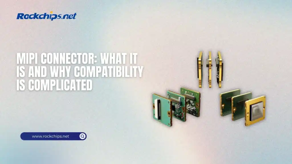
This is the main source of confusion. MIPI defines high-speed interfaces for components such as cameras and displays, but it does not give every development board and module a universal physical connector. Board manufacturers normally select their own FFC or FPC connector and assign its pins according to the hardware design.
As a result, a camera made for one single-board computer shouldn’t be connected to another board simply because the cable fits. Before choosing a module, you need to identify whether the port carries MIPI CSI-2 or MIPI DSI, check the pinout, confirm the number of data lanes, and verify the required power and control signals.
Table of Contents
- A MIPI Connector Is Not an Interface Standard
- Why the Same SoC Can Use Different Connectors
- Can a MIPI Connector Be Adapted?
A MIPI Connector Is Not an Interface Standard
The term “MIPI connector” is convenient, but technically incomplete. What you see on the board is usually a compact FFC/FPC connector. MIPI describes the communication interface carried through that connector.
The two interfaces most commonly encountered on single-board computers are:
- MIPI CSI-2, used primarily for camera sensors and imaging modules;
- MIPI DSI, used for LCD panels and other embedded displays.
These interfaces may use similar-looking ribbon cables, but they aren’t interchangeable. CSI-2 sends image data from a camera to the processor, while DSI carries display data in the opposite direction—from the processor to a screen. Their supporting signals, software requirements, and board-level routing are also different.
Modern processors can expose several MIPI camera and display pipelines at once. For example, the Rockchip RK3588 interface specifications include multiple MIPI CSI-2 inputs and MIPI DSI display support. But the processor’s capabilities don’t guarantee that every RK3588 board exposes all of them as usable connectors. The final layout depends on the board manufacturer, available pins, PCB routing, and the intended application.
Common MIPI Connector Types
Most single-board computers use small board-mounted FFC or FPC connectors for MIPI cameras and displays. These connectors are usually identified by their pin count and pitch—the distance between adjacent contacts. Common configurations include 15-pin, 22-pin, 24-pin, 30-pin, and 40-pin connectors, although many other layouts exist.
Pin count alone isn’t enough to determine compatibility. A 22-pin connector on one board may carry four MIPI data lanes, while another connector of the same size may use two lanes and reserve the remaining pins for power, I²C, reset, clock, or GPIO signals. The contact orientation also matters: some ribbon cables expose their contacts on the same side, while others place them on opposite sides.
There is therefore no truly universal MIPI cable. A cable can be mechanically correct but electrically incompatible with the board or module. Connecting it without checking the documentation may simply prevent the device from working, but an incorrect power pin can also damage the camera, display, or host board.
MIPI CSI and MIPI DSI Connectors
MIPI CSI connectors are intended for camera modules. In a typical CSI-2 implementation, the connector carries one or more high-speed data lanes, a clock lane, power rails, ground connections, and lower-speed control signals. I²C is commonly used to configure the image sensor, while additional pins may handle reset, power-down, or synchronization functions.
The number of lanes affects the available bandwidth. A basic camera may operate over two data lanes, while higher-resolution or higher-frame-rate sensors can require four lanes. However, more lanes don’t automatically mean that any high-resolution camera will work. The processor’s image signal processor, supported pixel formats, device-tree configuration, sensor driver, and available clocking must all match the module.
MIPI DSI connectors follow a similar physical principle but serve displays rather than cameras. Besides the high-speed DSI lanes, the connector may include power for the panel, I²C or SPI control, backlight control, reset, and touch-controller signals. This is why even displays with matching resolution and connector size aren’t necessarily interchangeable.
The available camera and display pipelines also differ considerably between Rockchip processors. Our comparison of the RK3566 and RK3588 differences shows why the SoC must be considered alongside the connector: both chips support embedded cameras and displays, but RK3588 provides a substantially more capable multimedia and multi-camera subsystem.
Pin Count Does Not Guarantee Compatibility
A common mistake is to search for a replacement camera or display using only the number of pins. That approach works for some established ecosystems, where manufacturers deliberately preserve a known connector layout, but it isn’t reliable across unrelated boards.
Before connecting a MIPI device, compare the following information:
The pinout should come from the board schematic, hardware manual, or official camera and display documentation. Product photos can help identify the connector, but they aren’t a reliable substitute for a pin diagram. Even when the electrical layout matches, the operating system still needs a compatible driver and correct hardware configuration.
Why the Same SoC Can Use Different Connectors
The processor determines how many MIPI interfaces can theoretically be supported, but the board designer decides which interfaces are actually available. One RK3588 board may expose several camera inputs and a separate display connector, while another may provide only one CSI port because the remaining lanes are used elsewhere or weren’t routed to physical connectors.
This distinction is especially important when selecting an SBC for computer vision, robotics, industrial inspection, or a multi-camera system. A specification such as “RK3588 with six camera inputs” describes the potential SoC configuration, not necessarily the connectors fitted to a particular board. The board schematic and hardware manual remain the final sources of truth.
The differences can be seen among current RK3588 single-board computer options. Boards based on the same processor vary in connector count, lane allocation, pin layout, and support for camera or display accessories. Choosing the SoC first and checking the physical interfaces later can therefore leave you with a board that has enough processing power but no practical way to connect the required sensor.
Can a MIPI Connector Be Adapted?
A passive adapter can work when two devices use the same electrical interface but arrange compatible signals differently. For example, an adapter board may convert between 15-pin and 22-pin CSI connectors or rearrange pins to match a particular camera ecosystem. In this case, the adapter changes the physical layout rather than the underlying protocol.
But an adapter can’t solve every compatibility problem; it won’t add two extra MIPI lanes to a host that only supports two, provide a missing sensor driver, or make a CSI camera operate through a DSI display port. Voltage differences, clocking requirements, and control-signal assignments must also be checked before an adapter is used.
Cable length presents another limitation – MIPI D-PHY was designed for high-speed communication over relatively short connections inside a device. Longer ribbon cables can introduce signal loss, interference, and timing problems, particularly at higher data rates. Industrial systems that place cameras farther from the processor often use serializer/deserializer solutions instead of extending a basic FFC cable.
References
- Official MIPI CSI-2 specification (MIPI Alliance)
- MIPI Display Serial Interface (MIPI Alliance)
- MIPI D-PHY physical layer (MIPI Alliance)
- FFC and FPC connectors (Molex)
